
.net

| Terms of service | ||||
|
Brokking |
.net |
Let's keep it simple |
|
|
|
Reviving a Clone Basecam brushless gimbal controllerA while ago I bought a cheap 2-axis brushless gimbal to get some test footage from my octocopter. I did not want to spend a huge amount of money because the octocopter was still in its test phase. And crashing a $300 is not my idea of fun.  Click to see the full image Click to see the full image
The firmware is preloaded and setup for a GoPro. And it works right out of the box as you can see in
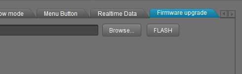
And then temptation comes into play when you see the "Firmware upgrade" tab. And how hard can it be? Download the latest firmware and click the flash button. And that's it.... literally. The board is dead or bricked as some like to call it. This is because the genuine Basecam boards run completely different software than the clone versions. It is the so called 'null' or cracked version of the earlier AlexMos/SimpleBGC software. The clone boards only communicate with the Basecam SimpleBGC GUI to get them setup. In short: the printed circuit boards are different and don't run the same firmware / software. 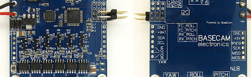 Click to see the full image Click to see the full image
Most people end up buying a new controller board for their gimbal. But there is another solution. With some patience it's possible to restore the original firmware to the clone board. The key is to reinstall the original firmware. But what is the original firmware? As I described before it is the 'null' or cracked version of the AlexMos/SimpleBGC software. After some searching I found the binary hex file for my own board and can be downloaded here:  SimpleBGC_2_2_b2_null.hex 79kB (ZIP file 30kB) SimpleBGC_2_2_b2_null.hex 79kB (ZIP file 30kB)
This firmware should work fine for most 2-axis cheap clone gimbals that worked with the Basecam SimpleBGC graphical user interface version 2.2 b2. But there are no guaranties! You will use this firmware at your own risk. In most cases the board is useless anyway so what do you have to lose? Next thing on the list is the tool to upload the firmware. For this I will be using the Arduino IDE. The processor on the gimbal controller is the same as on the Arduino Pro Mini so it's possible to reprogram this processor without any problems. Download the Arduino IDE here: Arduino IDE download site.
If you download the "ZIP file for non admin install" version you don't have to install it. When done you can easily remove it. Note: I'm using the Arduino 1.0.6 version in this example. Unzip the Arduino folder and copy it onto a USB stick. Do the same with the SimpleBGC_2_2_b2_null.hex file. 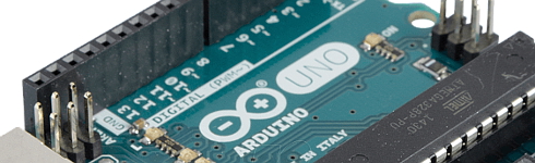 Click to see the full image Click to see the full image
And last we need some hardware to connect the gimbal controller processor (ATmega328P) to the Arduino IDE. In this case it's an Arduino Uno that will function as an in circuit programmer or ISP for short. Detailed information about how to program the Arduino Uno as an ISP programmer can be found here: Program Arduino as ISP programmer.
Now all the parts are gathered and we can start connecting all the parts. And this is the tricky part because not all the boards are the same. The basic principle however is very simple. Connect the following pins of the Atmega328P to the Arduino Uno board like this: 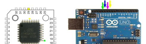 Click to see the full image Click to see the full image
In table form:
With most boards these Atmega328P pins are routed to connection pads. The manufacturer uses these pads to program the Atmega processor. In my case they are routed and marked on the edge of the board. Connecting them to the Arduino ISP looks something like this: 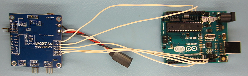 Click to see the full image Click to see the full image
Now it's time to flash the SimpleBGC_2_2_b2_null.hex file onto the Amega328P. I will use the Arduino IDE for this. The reason for using the Arduino IDE is the reliability and the fact that I don't like to suggest any programs that might contain malware. First thing to do is upload the bootloader to reset the fuse bits and check to see if everything is working correct.
For this go to:
Next select the right com port for the Arduino ISP:
And last select the correct programmer:
And finally click:
This will take a while and after a successful burn the message "Done burning bootloader" appears. This is a conformation that everything works fine and it's time to upload the SimpleBGC_2_2_b2_null.hex file. Now go to the command line and type:
Please note that this is one long continues command. For convenience I sliced it into readable pieces. Depending on the location (USB drive) of the Arduino folder and the location of the SimpleBGC_2_2_b2_null.hex file you might need to change the drive letter to the specific files. In the example I used drive E:. This might also be the case for the COM port where the Arduino ISP is connected to. Once the .hex file is uploaded successfully the board is alive and ready to use. 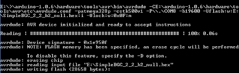 Click to see the full image Click to see the full image
|