
.net

| Terms of service | ||||
|
Brokking |
.net |
Let's keep it simple |
|
|
|
Project YMFC-32 - The STM32 quadcopter
The YMFC-32 is a STM32 based quadcopter that is easy to build and fun to fly. The auto level functionality makes it also a very capable starting quadcopter. Auto leveling means that, when you release the sticks the quadcopter levels itself. The total cost to build the YMFC-32 is approximately $135. Check step 2 below for a complete hardware list for all the individual parts. This includes a battery, transmitter, charger, resistors, etc. 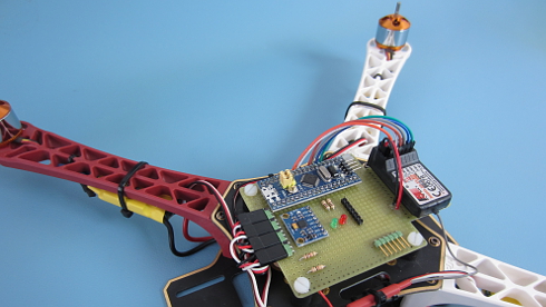
The YMFC-32 is not a high level flight controller. The purpose of the YMFC-32 is to provide a simple and understandable code that is needed to build a DIY quadcopter flight controller.
The code is well commented and clearly explained in the
If you encounter any problems during the build or setup please check the
Step 1 - SoftwareFirst download the complete YMFC-32 software package from the download section: And install the STM32 for Arduino add-on as shown in this video:
The STM32 for Arduino add-on that I used can also be downloaded form the download section. Step 2 - HardwareThe hardware needed for the YMFC-32 quadcopter is listed below. I made this hardware list for your convenience. This list is a suggestion and it's your own responsibility to ensure that the products meet your specific requirements. But this list should be sufficient to build the YMFC-32 quadcopter.
If you have never flown a quadcopter before I highly recommend the following quadcopter. It has the same control principle as the YMFC-32 but without the destructive energy. This way you can safely fly this thing indoors and practice your skills before flying the YMFC-32.
I personally prefer (and use) 8x4.5 inch props instead of the 10x4.5 inch props. This is to offload the motors and ESC's and to get a better response. Step 3 - The build
Watch the
Detailed pictures of my own YMFC-32 quad can be found in the
3.1 The voltage divider R3 & R4The resistors divide the flight battery voltage by 11. This way it is possible to measure the battery voltage during flight. The LED will light up when the battery voltage gets to low and the motor rpm automatically increases to compensate the dropping battery voltage during flight. The 1kΩ and 10kΩ resistors need to be installed otherwise the quadcopter will not fly perfect and the battery warning will not work. 3.2 The MPU-6050 gyro/accelerometer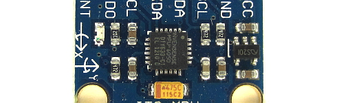 Click to see the full image Click to see the full image
The only gyro / accelerometer that is supported by the YMFC-32 software is the MPU-6050. This is because the auto-level feature requires an accelerometer and a gyro as I explain in these two videos:
The orientation of the gyro is very important! And make sure that the Z-axis is vertical (perpendicular to the surface) and the edges of the gyro are aligned with the edges of the quadcopter. Click on the image to see the gyro orientation. 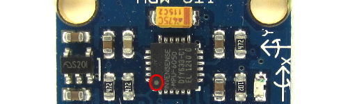 Click to see the full image Click to see the full image
If the gyro is mounted in the wrong orientation the quadcopter will flip upside-down immediately. Mount the gyro with thin double side tape. Don't use foam tape or any other dampening material. This will decrease the performance. 3.3 The tranmitter and receiver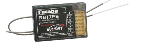 Click to see the full image Click to see the full image
Unlike the
The transmitter must have adjustable endpoints and subtrims. So make sure to check the manual of the transmitter for these specific functions. The transmitter that I use myself is this:  Flysky FS-T6 6-CH TX Transmitter Flysky FS-T6 6-CH TX Transmitter
The YMFC-32 needs standardized receiver pulses as described in the table below.
Connect the roll (aileron), pitch (elevator), yaw (rudder) and throttle output of the receiver to the STM32 ports A0, A1, A2 and A3. The order is very important. Check the manual of the transmitter / receiver to see which receiver port is connected to the specific function. The receiver is powered by the +5V output of the BEC. The connection can be found on the schematic. If you want to know how the STM32 reads the receiver signals, watch this video:
3.4 The ESC's Click to see the full image Click to see the full image
On the schematic only the ground and the signal wires of ESC 2,3 and 4 are connected. This is correct. The +5V (BEC) from ESC 1 is connected and provides power for the flight controller. If your ESC does not have a built-in BEC/+5V you need to provide power via a 5V step down regulator that is connected to the flight battery.
The signal wire of the ESC's are connected to the digital outputs B6, B7, B8 and B9 of the Arduino as shown in the table below. Also check the direction of rotation.
If you want to know how the ESC is controlled by the STM32, watch this video:
Step 4 - Run the setup softwareRemove the props, don't connect the flight battery and upload the hardware test program to the STM32. Watch:
Test all the hardware functions as explained in the video. Make sure that the transmitter is setup correctly with 1000us till 2000us endpoints and a 1500us center position. Electronic speed controllers or ESC's for short are controlled with a 1000us till 2000us pulse. 1000us means off and 2000us means full throttle. To make sure that all the ESC's react the same way it's important to calibrate the 1000us and 2000us point. Without calibration the motors will perform different and the quadcopter doesn't fly well or might even crash. Remove the props and upload the hardware test program to the STM32. Disconnect the USB cable. With all the ESC's connected you can follow the instructions in the manual to calibrate the ESC's all at once. In most cases this is done with the following steps:
But again, check the manual of your specific ESC for the correct calibration procedure. Step 5 - balance the motors and propsWatch:
SAFETY NOTE: 5.1 Why is balancing the props important?Balancing the props is incredibly important! Without well balanced props and motors the gyro and accelerometer will produce noise that makes the motors react jerky. There is minimal stability and the quadcopter can't level itself. To get the best performance the props and motors need to be balanced perfectly. Putting the gyro / accelerometer on vibration dampeners does not help and can only make things worse. 5.2 How to balance the props by using the YMFC-32 softwareMount the props on the motors and check if the counter clock wise and clock wise props are in the right position. Upload the hardware test program and open the Arduino serial monitor at 57600baud. Send '1' via the serial monitor and wait for the response "Test motor 1 (right front CCW.)". The numbers that are printed on the screen represents the amount of vibration measured by the accelerometer. This is not a standardized value and should only be used to minimize the amount of vibration of your YMFC-32 quadcopter. Hold the quadcopter firmly down, place the throttle in the lowest position and connect the flight battery. Now slowly increase the throttle until motor 1 starts to spin. Check the direction of rotation and that the prop produces upward thrust. If the motor rotates in the wrong direction you need to switch two of the three motor wires. Put the throttle in the lowest position to stop the motor. Now hold the motor frame firmly in your hand and increase the throttle to half throttle. Check the numbers on the screen and also memorize the vibrations that you feel with you hand that is holding the motor frame. 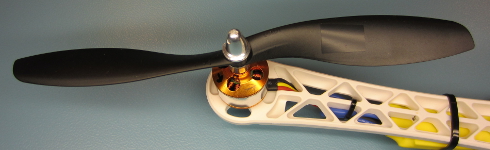 Click to see the full image Click to see the full image
Stop the motor and put a small piece of tape on one of the blades and run the test again. Check if the vibrations reduce. If nor try a piece of tape on the other blade. Keep doing this until the motor and prop run as smooth as possible. This can sometimes be a daunting task but the reward is a very stable flying quadcopter. So take your time and get it perfect! When you are done with motor 1, send a 'q' to quit and repeat the process for motors 2, 3 and 4. Step 6 - Calibrate the IMU (gyro and accelerometer)Calibrating the IMU makes the quadcopter fly as level and stable as possible. So please make sure to pay attention to this chapter. 6.1 Calibrating the accelerometerPlace the quadcopter on a spirit level surface and upload the setup program to the STM32. Open the Serial monitor and send an h via the serial monitor. This will initiate the calibration of the gyro and the accelerometer. Don't move the quadcopter during calibration. When finished the following lines are printed on the serial monitor: Please note that your values are different and MPU-6050 depending. The values can be negative an positive. Make sure to store these values for later use. The first two values represent the pitch and roll offset of the accelerometer. These values are used to determine the level position of the quadcopter when you release the sticks of the transmitter. When these values are not setup correctly the quadcopter will drift unnecessarily more than with correct values. In the YMFC-32 setup program and in the YMFC-32 flight controller program these accelerometer calibration values must be entered in the following lines: The calibration of the accelerometer is needed: After the building the quadcopter. When you change the gyro or gyro position. After a crash. 6.2 Calibrating the gyroThe last tree values that where obtained with the setup program represent the pitch, roll and yaw offset of the gyro. These values are used to calculate the angle of the quadcopter. When these values are not setup correctly the pitch and roll angles of the quadcopter are not calculated correctly and the quadcopter will drift unnecessarily more than with correct values. In the YMFC-32 setup program and in the YMFC-32 flight controller program these gyro calibration values can be entered in the following lines: The use_manual_calibration variable holds a key feature. The advised or stock setting is false. This means that the manual calibration values are not used and that the gyro is calibrated automatically before every flight. When the use_manual_calibration variable is set to true the manual entered gyro offset values are used and the gyro is not calibrated automatically at startup. So when you connect the flight battery the green LED goes on immediately. This saves time and might be useful when you start the quadcopter from a moving object. The downside is that the gyro offset changes when the ambient temperature changes. These changes can be significant enough to cause unnecessarily drifting of the quadcopter. That is why it's always best to use the automated gyro calibration and set the use_manual_calibration to false. If you want to use the manual calibration values makes sure to calibrate the gyro at the same temperature as when the quadcopter is flying. If you want to use the manual calibration of the gyro, you need to calibrate it: After the building the quadcopter. When you change the gyro or gyro position. After a crash. When the temperature is changing +/- 5 degrees Celsius. Step 7 - Upload the flight controller softwareDisconnect the flight battery and upload the flight controller software to the STM32. Disconnect the USB cable and connect the flight battery. Hold the quadcopter firmly in your hand and start the motors with the following sequence:
Start = throttle down and yaw left 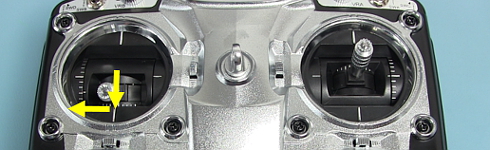 Click to see the full image Click to see the full image
Increase the throttle up to the point when the quadcopter almost starts to become weightless. The quadcopter should now try to level itself. If you move the quad it should start to counteract the movement until it is level again. When the roll or pitch stick of the transmitter is moved the quadcopter should move in the same direction. If this is not the case redo the setup procedure and double check all the points on this page. When all is good it is time for a careful first test flight. Always fly the quadcopter outdoor and over grass for safety. Grass will minimize the damage during a crash. 8 - The status LEDsDuring startup and flight the status LEDs provide valuable information as shown in the picture below: 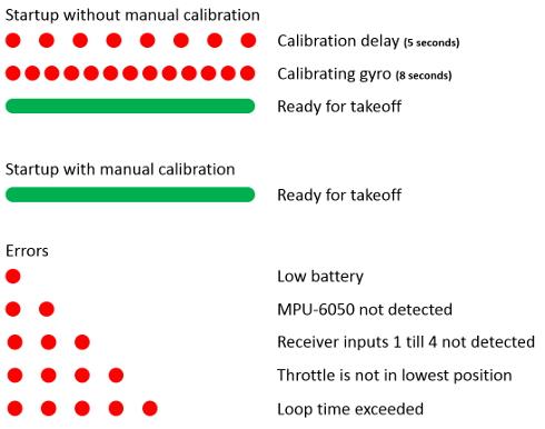 Click to see the full image Click to see the full image
Step 9 - Improve PID settingsIf necessary improve the standard PID settings. Watch the following video if you want to learn more about PID controllers:
|
|||||||||||||||||||||||||||||||||||||||||||||||||||||||||||||||||||||||||||||||||||||||||