
.net

| Terms of service | ||||
|
Brokking |
.net |
Let's keep it simple |
|
|
|
From an Arduino quadcopter to a versatile RPAS / drone
Have you ever considered to build and program your own multicopter, drone or RPAS (Remotely Piloted Aircraft System)? I did and this is a summarized story about how I build and programmed my own octocopter RPAS / drone. 
January 6, 2014
This is a project that I started on January 6, 2014 as a winter project. Too cold to fly my
So I started my journey and got the first quadcopter to fly on February 2, 2014.
February 2, 2014
In this video the Arduino based flight controller only uses a gyro to stabilize the quadcopter. The software is basically the same as the
But what's a multicopter without an auto level function? This means that the pilot does not have to keep the multicopter level. This was a pretty big challenge because the algorithm that combines the gyro and accelerometer is pretty complex at first glance. After reading articles about Inertia Measurement Units or IMU for short, I noticed that there is a lot of talking about Kalman filters. After studying Kalman filters and trying to make sense of all the madness I boldly decided that there must be an easier way to make an IMU for a multicopter. After some sleepless night and banging my head against the wall I got it! Keep in mind that I don't use any other code like MultiWii or Aeroquad to figure it out. I just looked at the gyro and accelerometer data for hours and tried several ways to get the right algorithm.
On February 8, 2014 I got it working! Very rude and nasty code but the principle worked as you can see in the video.
February 8, 2014And then I made the misassumption that the hard part was over. Boy, was I wrong. The next step that I worked on was an altitude hold function so the quad will stay at the same altitude when the throttle is released. To get this done I used the MS5607 barometer from Measurement Specialties. This pressure sensor is capable of detecting altitude differences of 20cm.
On February 22, 2014 I made the
And on March 20, 2014 I got it up and running. The altitude hold function performed perfect.
March 20, 2014Now that the quad stays level and maintaining its altitude it is time for the next big step, autonomous flight. For this the quadcopter needs to know its 3D position. The extra sensors that I added to achieve this are a compass and a GPS module. With these sensors the quadcopter knows its latitude and longitude position. It also knows the correct direction to keep its current latitude and longitude position.
It sounds simple but it is pretty tough to get this done. A very good GPS module really improves the process. I started with a LS20031 GPS module and made my first successful autonomous flight on April 19, 2014.
April 19, 2014Ok, the autonomous quadcopter was born. But the position hold results weren't that good though. So I tried another GPS module, the u-blox LEA-6S. Just to see if I can increase the accuracy of the position hold function. And it was possible! After some algorithm challenges and lots of test flights I finally got the position hold results that I was looking for. So it was time for the next step: send the quad to a predefined position or waypoint.
I finished the implementation of the code for the quadcopter and the telemetry transceiver on June 16, 2014. With the help of the telemetry box I can now send the quadcopter to any position that I want. Even in stronger wind conditions.
June 16, 2014And now you might think: that's it, you're done. Well.... not quite. I only got the basic principles working and the hardware is still a mess. In the following months I reorganized the software. As some already know, the Arduino code is easy to use but awful slow and bulky when it comes to execution speed and program size. So I took out the Arduino software and wrote all the software myself. Even the timers, serial output and Wire library where rebuild from the ground up. After several months of programming and testing I finished the code and added more features like:
This was the most time consuming action I have done during this project. But it was well worth it. I now had a fully functioning flight controller with a program size of just 28KB and a real update frequency of 250Hz.
Now that I knew that it's possible I took the next step: rebuild the hardware.
December 30, 2014The next thing that was on my wish list: get rid of the Arduino. There is nothing wrong with it and it performed amazingly well during all the test flights that I made. But as you can see in the previous video I stacked all the parts on shields. The whole stack is hold together with Velcro straps. Not a very clean way to do it. So I started to design my own printed circuit board or PCB for the flight controller. I started with a single layer through hole PCB so I could hand solder it at home. And as you can guess, this was not a good idea. There was a lot of interference and the board was unreliable.
So I was back to where I started. Taking the big leap I designed a two layer board. This one was manufactured by a professional company and the result was stunning. Now I only had to learn to solder smd parts.
July 10, 2015The board is finished and everything is working like a charm. And you guested it: time for the next step. I wanted to build and octocopter because it has motor and ESC redundancy. This way it is also possible to carry some heavier cameras and gimbals. I already made eight outputs for the octocopter motors on the PCB. Making parts for the octocopter by hand takes a lot of time and introduces errors. So I rebuild my Proxxon micro mill to a cnc version. This way it is easier to make de booms of the octocopter without any errors. On the same milling machine I made the top and bottom center plates. The rest of the parts were made with a fretsaw and a cordless compact drill.
And on October 8, 2015 the octocopter flew for the first time.
October 8, 2015As you can see in the video the octocopter fly's really stable and the video footage is not bad at all. After hours of flying I was very happy with the results. It's hard to believe that it all started as a temporary winter project. The downside of painted plywood is of course the weight. Lighter material that is commonly used for multicopters is carbon fiber. The downside of carbon fiber is that it is very difficult to machine. So after some thinking I purchased a CNC router and learned how to manufacture carbon fiber parts myself. And this was a very big success.
After hours of engineering and cutting the parts the new frame was ready.
February 19, 2016Now that I made a decent frame it's time to look forward on what to do next. I came this far so why not try to build a multicopter that could pass the RPAS airworthiness test. That should be fun. But as expected, it is a little more involved that you might think. But let's start simple. In the assessment specification for remotely piloted aircraft systems it becomes clear that a decent current measurement system is necessary. So I started to design a new printed circuit board that can measure the current of every esc. Most ESC's have a current limiting function. A common problem is that in most cases the ESC's are overrated. They can provide more current and have the ability to overheat the motor. So in case of a mechanical failure the current will slowly rise above the maximum rated current of the motor. Causing it to overheat. There is now a big chance of a short circuit. 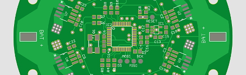 Click to see the full image Click to see the full image
With this new board the flight controller is able to shut down the motor before it's getting to hot. Preventing the worse. The exact same thing is done with industral motors. And as said before, the octocopter has ESC/motor redundancy. Shutting down a motor during flight to prevent a short circuit is much safer. The octocopter keeps flying and the pilot can still safely land.
Combining this with the already available battery voltage the possibilities are limitless. For example, the pilot gets a warning when one motor has consumed significantly more energy than the other motors during the complete flight. A quick maintenance check can prevent serious problems in the future.
March 17, 2016The ESC interface board is ready and working as expected. Because this PCB is part of a larger development I cannot mount it yet. My current flight controller is communicating via I2C while this board needs SPI communication. 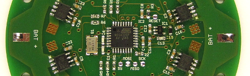 Click to see the full image Click to see the full image
The next board that I will (re)design is the flight controller. The reflow hot plate is working fine and I can now design a PCB with the tiny LGA sensors directly on the PCB. Exciting challenge! Stay tuned!
|
 RC helicopters