
.net

| Terms of service | ||||
|
Brokking |
.net |
Let's keep it simple |
|
|
|
Project YMFC-32 autonomous
The YMFC-32 autonomous flight controller projectThe YMFC-32 autonomous is an STM32 quadcopter flight controller that was programmed with the Arduino IDE. Its purpose is to create an educational project that can be used as a hobby or school project. The main goals of this project are:
In short, you can build the complete YMFC-32 autonomous for under €200,-. This includes a battery, charger, remote control and a telemetry system. The Arduino/STM32 code can be downloaded for free in the download section.  Click to see the full image Click to see the full image
The flight controller code is commented and clearly explained in the
If you encounter any problems during the build or setup please check the
Table of contents
The YMFC-32 autonomous holds the following features:
With my own quadcopters I get a flight time between 15 till 20 minutes with a 3800mAh 3 cell lipo. You can find more information about my testquads on the background infromation (bain) page
First download the complete YMFC-32 software package from the download section: And install the STM32 for Arduino add-on as shown in this video:
Please note that the STM32 for Arduino add-on is a work under construction and I have no influence on any changes they make. If you have any questions about the STM32 for Arduino add-on, please visit this forum:
If you have any problems with the latest STM32 for Arduino add-on you can find the add-on that I used in the
The hardware needed for the YMFC-32 autonomous is listed below. I made this hardware list for your convenience. This list is a suggestion and it's your own responsibility to ensure that the products meet your specific requirements. But this list should be sufficient to build the YMFC-32 quadcopter. Please note: All sensors need to be present. Otherwise the YMFC-32 flight controller code will not work!
I personally prefer (and use) 8x4.5 inch props instead of the 10x4.5 inch props. This is to offload the motors and ESC's and to get a better response.
If you have never flown a quadcopter before I highly recommend the following quadcopter. It has the same control principle as the YMFC-32 but without the destructive energy. This way you can safely fly this thing indoors and practice your skills before flying the YMFC-32.
Watch the
Detailed pictures of my own YMFC-32 quadcopter can be found in the
The resistors divide the flight battery voltage by 11. This way it is possible to measure the battery voltage during flight. The LED will light up when the battery voltage gets to low and the motor rpm automatically increases to compensate the dropping battery voltage during flight. The 1kΩ and 10kΩ resistors need to be installed otherwise the quadcopter will not fly perfect and the battery warning will not work.
 Click to see the full image Click to see the full image
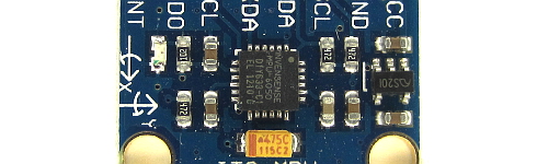
The only gyro / accelerometer that is supported by the YMFC-32 software is the MPU-6050. This is because the auto-level feature requires an accelerometer and a gyro as I explain in these two videos:
The orientation of the gyro is very important! And make sure that the Z-axis is vertical (perpendicular to the surface) and the edges of the gyro are aligned with the edges of the quadcopter. Click on the image to see the gyro orientation. 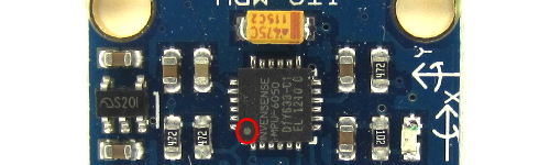 Click to see the full image Click to see the full image
If the gyro is mounted in the wrong orientation the quadcopter will flip upside-down immediately. Mount the gyro with thin double side tape. Don't use foam tape or any other dampening material. This will decrease the performance.
 Click to see the full image Click to see the full image
Unlike the
The transmitter must have adjustable endpoints and subtrims and a PPM output. So make sure to check the manual of the transmitter for these specific functions. The transmitter that I use myself is this:  Flysky FS-T6 6-CH TX Transmitter Flysky FS-T6 6-CH TX Transmitter
The Flysky T6 has no PPM output. For this I made a PWM to PPM converter that will work with the R6B receiver. You can find more information on
A transmitter with PPM output that works right outof the box is this : Flysky FS-i6X transmitter with IA6B Receiver
The YMFC-32 needs standardized receiver pulses as described in the table below.
Use the table below for the flight modes and the head lock functions. Check the various functions with the telemetry system.
Connect the PPM output of the receiver to the STM32 port A0. Check the manual of the transmitter / receiver on how to use or activate the PPM output of the specific receiver. The receiver is powered by the +5V output of the BEC. The connection can be found on the schematic. If you want to know how the STM32 reads the receiver signals, watch this video:
 Click to see the full image Click to see the full image
On the schematic only the ground and the signal wires of ESC 2,3 and 4 are connected. This is correct. The +5V (BEC) from ESC 1 is connected and provides power for the flight controller. If your ESC does not have a built-in BEC/+5V you need to provide power via a 5V step down regulator that is connected to the flight battery.
The signal wire of the ESC's are connected to the digital outputs B6, B7, B8 and B9 of the Arduino as shown in the table below. Also check the direction of rotation.
If you want to know how the ESC is controlled by the STM32, watch this video:
 Click to see the full image Click to see the full image
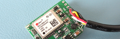
The GPS/compass module is needed for the heading lock and GPS hold function. The module that I'm using and that is linked in the parts list, is used for the Ardupilot or APM flight controller. Make sure that it has a HMC5883L compass built-in. Most modules will hold the u-blox M8N chipset. Well-designed modules will give you very stable and accurate GPS hold results as shown in this video:
Please note that the YMFC-32 uses the u-blox protocol to setup the module. If you don't have a genuine u-blox module the GPS hold function might not work as expected. More information about counterfeit products can be found here: Counterfeit products and u-blox brand misuse
Connections can be made according to the schematic. Please note that the colors of the wires may be different per module. If you have any doubts about the wire functions you can always open the module and check the markings on the printed circuit board.
 Click to see the full image Click to see the full image
The MS5611 barometer is used for the altitude hold function. It's a very sensitive pressure sensor that can detect pressure differences within a 10cm accuracy. Important to know is that this MS5611 is light sensitive and must be protected against sunlight. I made a video about programming the altitude hold function and how to setup the MS5611 on the quadcopter. Please check these videos for more information about the GPS hold function:
The listed hardware and connections on the schematic are the bare minimum. So please don't try to fly the YMFC-32 without the listed hardware or connections.Always double check everything before you power the system for the first time. When the hardware is built exactly the same as shown on the schematic you need to remove the props, don't connect the flight battery and upload the hardware test program to the STM32.
Open
Test all the hardware functions as explained on the "Explaining the YMFC-32 autonomous setup program" page. Electronic speed controllers or ESC's for short are controlled with a 1000us till 2000us pulse. 1000us means off and 2000us means full throttle. To make sure that all the ESC's react the same way it's important to calibrate the 1000us and 2000us point. Without proper ESC calibration the motors will perform different and the quadcopter doesn't fly well or might even crash. Remove the props and upload the hardware test program to the STM32. Disconnect the USB cable. With all the ESC's connected you can follow the instructions in the manual to calibrate the ESC's all at once. In most cases this is done with the following steps:
But again, check the manual of your specific ESC for the correct calibration procedure.
SAFETY NOTE:
Balancing the props is incredibly important! Without well balanced props and motors the gyro and accelerometer will produce noise that makes the motors react jerky. There is minimal stability and the quadcopter can't level itself. To get the best performance the props and motors need to be balanced perfectly. Putting the gyro / accelerometer on vibration dampeners does not help and can only make things worse.
Mount the props on the motors and check if the counter clock wise and clock wise props are in the right position as stated in the table below:
Upload the hardware test program and open the Arduino serial monitor at 57600baud. Send '1' via the serial monitor and wait for the response "Test motor 1 (right front CCW.)". The numbers that are printed on the screen represents the amount of vibration measured by the accelerometer. This is not a standardized value and should only be used to minimize the amount of vibration of your YMFC-32 quadcopter. Hold the quadcopter firmly down, place the throttle in the lowest position and connect the flight battery. Now slowly increase the throttle until motor 1 starts to spin. Check the direction of rotation and that the prop produces upward thrust. If the motor rotates in the wrong direction you need to switch two of the three motor wires. Put the throttle in the lowest position to stop the motor. Now hold the motor frame firmly in your hand and increase the throttle to half throttle. Check the numbers on the screen and also memorize the vibrations that you feel with you hand that is holding the motor frame. 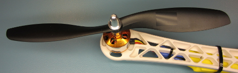 Click to see the full image Click to see the full image
Stop the motor and put a small piece of tape on one of the blades and run the test again. Check if the vibrations reduce. If nor try a piece of tape on the other blade. Keep doing this until the motor and prop run as smooth as possible. This can sometimes be a daunting task but the reward is a very stable flying quadcopter. So take your time and get it perfect! When you are done with motor 1, send a 'q' to quit and repeat the process for motors 2, 3 and 4. In this video I'm showing the balancing procedure:
When you are convinced that everything is working as expected you can upload the flight controller software to the STM32. Don't connect the flight battery yet. Make sure to set the correct declination befor uploading the code. All the other settings can be ignored for now. Turn on the transmitter, the telemetry receiver and power the flight controller via the USB/FTDI programmer. Don't move the quadcopter during calibration (fast blinking). The LEDs on the quadcopter should now start to blink according to the sequence as shown below. If the LED indication is not the same as shown below please check step 8 (The status LEDs).
After the startup sequence the flight controller information should be printed on the telemetry system. You can now test the flight mode switch and the heading lock switch. Go to the pitch and roll angle page on the telemetry receiver and check the angles of the quadcopter.
By calibrating the accelerometer you can set the angles to zero when the quadcopter is level. Calibrating the accelerometer is only needed after every upload of the code, the first build or after a crash. Place the quadcopter on a spirit level surface and move both sticks to the top left corner. 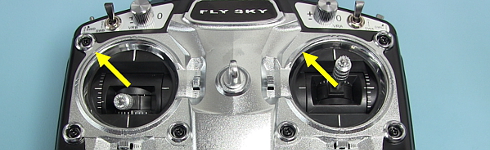
After that the LED will blink, indicating that the calibration procedure is finished. If the accelerometer offset is to large an alarm is generated. Please check question 13 on the
The compass calibration procedure needs to be executed:
The goal of the calibration is to remove the offset of the compass module and center the X, Y and Z-axis. Please note:
First you need to know where the magnetic North is. You can check this with a compass app or a magnetic hand compass. To start the compass calibration move both transmitter stick to the top right corner. The red LED will light solid indicating that the calibration procedure is started. 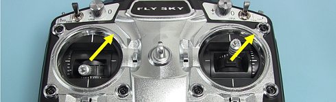
Rotate the quadcopter around the roll and pitch axis in the direction of the magnetic North. A minimum of two rotations per axis is needed. When finished move the pitch stick down. The LED will blink, indicating that the compass calibration is completed. You can find detailed information about the compass calibration procedure in this video:
Always check the compass with the telemetry system after calibration. With the correct declination the compass should point in the geographic North direction when the heading is 0 degrees.
Now it's time for the first test flight. Find a nice park lawn with low cut grass. Grass will minimize the damage during a crash. Never fly the quadcopter indoors for the first time! Now go through the preflight checklist.
01. Is the MPU-6050 mounted with the dot to the left rear?
Start = throttle down and yaw left 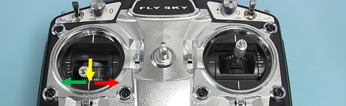
Start the quadcopter and increase the throttle up to the point when the quadcopter almost starts to become weightless. The quadcopter should now try to level itself. Increase the throttle and fly it as low as possible for at least the first battery. Check if the quadcopter is flying with the stick around the center position. Approximately 1400 till 1600us throttle pulse should work fine (+/- 20% center stick position). When everything is working and the quadcopter flies stable you can land and disconnect the flight battery. Don't test the other flightmodes yet.
Find the following line in the setup section of the flight controller code and change:
into: This will activate the automatic take-off detection. If the automatic take-off detection function is working correct the quadcopter should automatically fly with the throttle stick almost in the center position.
Also set the correct declination in this line: You can use this map as a reference:
Now you can upload the code to the STM32 and calibrate the accelerometer and compass as described before. Put the quadcopter on grass and start the motors with the start sequence. Increase the throttle to half way. The motors should now increase their rpm and the quadcopter will take-off automatically. When the quadcopter takes off the throttle is registered and set as a base hover throttle. The quadcopter should now hover with the throttle stick in the center position.
If this is not the case you can check question 15 on the
When the quadcopter is flying with the throttle stick close to the center position is now possible to activate the altitude hold function. Depending on the location of the pressure sensor it might be necessary the adjust the PID values. Please check this video for more information about the altitude hold function:
When the altitude hold function is working you can activate the GPS hold function. With this function activated the quadcopter will hold its position fully autonomous. Please note that it is not possible to relocate the quadcopter with the control sticks. For safety it is possible to overrule the GPS hold controller. This way it is always possible to get the quadcopter back. However, if something is wrong it's always best to deactivate the GPS hold function immediately. Please check these videos for more information about the GPS hold function:
The last feature to test is the head lock function. This function is really useful and prevents that the pilot loses orientation. Normally the forward direction of flying is the nose direction. By using the head lock function the forward direction is the same as the take-off nose direction. 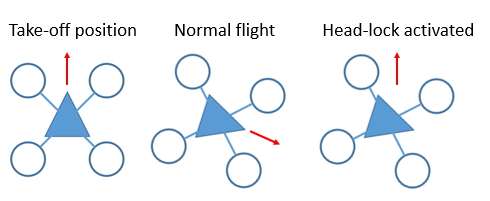
The red arrow indicates the forward (stick forward) flight direction.
During startup and flight the status LEDs provide valuable information as shown in the picture below:
A more detailed explaination of the errors can be found on the
|
|||||||||||||||||||||||||||||||||||||||||||||||||||||||||||||||||||||||||||||||||||||||||||||||||||||||||||||||||||||||||||||||||||||||||||||||||||||||||||||||||||||||||||||||||||||||||||||||||||||||||||||||||||||||||||||||||||||||||||||||||||||||||||||||||||||||||||||||||||||||||||||||||||||||||||||||||||||||||||||||||||||||||||||||||||||||||||||||||||||||||||||||||||||||||||||||||||||||||||||||||||||||||||||||||||||||||||||||||||||||||||||||||||||||||||||||||||||||||||||||||||||||||||||||||||||||||||||||||||||||||||||||||||||||||||||||||||||||||||||||||||||||||||||||||||||||||||||||||||||||||||||||||||||||||||||||||||||||||||||||||||||||||||||||||||||||||||||||||||||||||||||||||||||||||||||||||||||||||||||||||||||||||||||||||||||||||||||||||||||||||||||||||||||||||||||||||||||||||||||||||||||||||||||||||||||||||||||||||||||||||||||||||||||||||||||||||||||||||||||||||||||||||||||||||||||||||||||||||||||||||||||||||||||
 Click to see the full image

