
.net

| Terms of service | ||||
|
Brokking |
.net |
Let's keep it simple |
|
|
|
PWM to PPM converter for the Flysky R6B receiverThe YMFC-32 autonomous needs a minimum of 6 channel PPM signal as a control input. This means that you cannot use a standard receiver that has 6 individual PWM outputs like the Flysky R6B. This receiver comes with the Flysky T6 transmitter that was in the material list of the YMFC-AL. To make sure that everybody who has a Flysky T6 with a R6B receiver can also build the YMFC-32 a simple PWM to PPM signal converter is needed. The partsThe parts that are needed:
The schematicThe schematic: 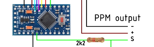 Click to see the full image Click to see the full image
The resistors are needed to divide the 5V from the Arduino to 3V. The STM32 is a 3.3V microcontroller and cannot handle 5V on the A0 input. The R6B receiver outputs the PWM signals as followed: 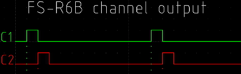 Click to see the full image Click to see the full image
The Arduino program will detect the rising flanks of the various channels and create a small pulse on every rising flank of 100 µs. After the last rising flank of channel 6 a stop pulse is created on the falling edge of channel 6. This is the lower green line on the image. The Arduino programThe code for the Arduino pro mini can be downloaded here:  pwm_to_ppm_r6b.zip pwm_to_ppm_r6b.zip
Some background informationThe signal itself is a series of pulses of fixed length. Between these pulses are pauses of varying length. The information on this type of signal is encoded as the length of a pulse plus the length of the following pause. Or in other words: the time between the start of two pulses (or end, doesn't matter since the pulse is of fixed length). This is also the reason it doesn't matter whether the pulse is high or low; you simply pick either the rising or falling edge of a signal and measure the time between two rising or falling edges. Channels follow each other in chronological order in the signal; i.e. channel 1 comes first, channel N last. The time between the pulses is used to generate a PWM signal. Pulses are usually around 500 microseconds in length, the pauses somewhere between 500 and 1500 microseconds. Add those together and you get channel values of 1000 to 2000 microseconds, which happens to be the same range as used in Servo Signals. After the last channel there's an End Of Frame (or Beginning Of Frame) pause. This pause is somewhere between 5000 and 20000 microseconds in length; receivers don't seem to be very strict with this. The pause may be of varying length, this way you can pad a frame to a fixed length.
|