
.net

| Terms of service | ||||
|
Brokking |
.net |
Let's keep it simple |
|
|
|
MPU-6050 6dof IMU for auto-leveling multicoptersAuto leveling a multicopter is pretty challenging. It means that when you release the pitch and roll controls on your transmitter the multicopter levels itself. To get this to work the flight controller of the multicopter needs to know exactly which way is down. Like a spirit level that is on top of the multicopter for the pitch and roll axis. Very often people ask me how to make an auto level feature for their multicopter. The answer to a question like this is pretty involved and cannot be explained in one email. And that is why I made this video series. In this video series I will explain how to program a simple 6 degree of freedom inertial measurement unit or 6dof IMU for short that makes it possible to create an auto-level feature for a multicopter.
The folowing hardware is used for this project: Funduino pro mini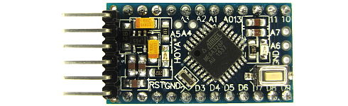 Click to see the full image Click to see the full image
MPU-6050 gyro / accelerometer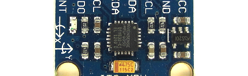 Click to see the full image Click to see the full image
LCD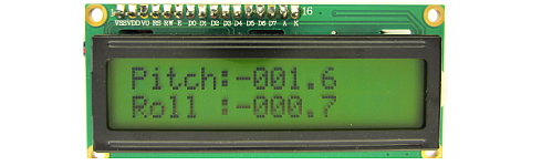 Click to see the full image Click to see the full image
Auto leveling a multicopter is pretty challenging. It means that when you release the pitch and roll controls on your transmitter the multicopter levels itself. To get this to work the flight controller of the multicopter needs to know exactly which way is down. Like a spirit level that is on top of the multicopter for the pitch and roll axis. Very often people ask me how to make an auto level feature for their multicopter. The answer to a question like this is pretty involved and cannot be explained in one email. And that is why I made this video series. In this video series I will explain how to program a simple Inertial measurement unit or IMU for short that makes it possible to create an auto-level feature for a multicopter. To get an idea of what to expect during this video, I will explain Euler angles, the Kalman filter, gimbal lock and finally finish the video with something like this. Of course not, haven't you seen my website: let's keep it simple? It might not be the most sophisticated IMU but it will do fine. By the way, it's the same principle as I used in this video. So without further ado let's start with the hardware. In this video series I will be using the MPU-6050. Now, I don't use this gyro in my own flight controller for various reasons. But I'm using the MPU-6050 during this video series because it's very easy to obtain for my viewers. It's also very cheap and it holds a gyro and an accelerometer in one package. This is very convenient when programming an IMU. With this video, and most of my other videos I'm trying to make my viewers smarter. This means that we also need to cover the basics. And I will start with the gyro. The gyro only measures angular motion and is measured in degrees per second. Or something similar like that. But it's always angular motion over time. The angular motion on the multicopter is everywhere the same. So it does not matter where the gyro is located. But it's always a good idea to mount the gyro in the center of the quad where, most of the time, the vibrations are lowest. To know the exact output of the MPU-6050 gyro we need to have a look in the datasheet. It states here that the output will be 65.5 when the angular motion of the gyro is 1 degree per second. This is, if we use the 500dps full scale. Which I will use during this video. The output of the gyro is a 16 bit signed value which is similar to the Arduino integer. This means that the variable, where the raw data is stored, needs to be declared as an integer. So, the output is 65.5 when the gyro is rotating 1 degree per second. If I rotate the gyro around it's yaw axis and complete the turn in exactly one minute, the output of the gyro at any moment during that turn is 393. This is because with every second the gyro moves 6 degrees. So 6 times 65.5 equals 393. For convenience I will convert the output of the gyro to degrees per second. In Arduino code it will be angle_in_degrees = raw_gyro_output divided by 65.5. The angle in degrees during this video will be a float so we can handle the decimal point. And when the angular rotation of the gyro is 500dps the raw data output of the gyro is 500 times 65.5 witch equals 32750. This is almost the maximum value of an integer as we can read on the Arduino page. Before the fun part really starts it's important to know that the gyro needs to be calibrated before use. Here you can see the raw values that I poll from the gyro. Despite the fact that the gyro does not move the output implies that the gyro is moving. To get the best results the output of the gyro needs to be set to zero. This is done by simply take the average offset from multiple readings and subtract this from the raw output. This is done in this small piece of code here. It will calculate the average of 2000 gyro readings and stores these values for later use. It's the same code as I used for the YMFC-3D flight controller. Next thing that I like to do is to make a graph of the gyro data when it is mounted on this test setup. This setup will simulate the vibrations of the multicopter when it is flying. This is just an example and the values may vary for each multicopter. I will plot the angle in degrees per second of one gyro axis onto the serial plotter of the Arduino IDE. Before the motor is running and after calibration the output of the gyro is almost zero all the time. When the motor is running the gyro will output larger differences despite the fact that the gyro isn't moving. This is caused by the vibrations of the motor and prop. Ok, were almost done so stay with me for just a few moments. As we already discussed, the output of the gyro is degrees per second. So what happens when I add all the raw gyro output values every second? Let's take our one minute rotation example. At any moment in time the output is 393 as I explained before. Now what value do I get when I add 393 every second. This will be 23580. But what does this mean. Well let's divide this value by 65.5. Indeed, we get a value of 360 degrees. So by adding all these gyro values over time, which is called integrating, it is possible to calculate the total angle that the gyro has traveled. This is starting to get fun, right. If I take the YMFC-3D flight controller for example, the refresh rate is 250Hz or every 4us. So it's possible to integrate the gyro's output every 4us instead of every 1 second. This means that we have to divide the raw gyro data by 250. And after that divide it again by 65.5 to get the traveled angle. In Arduino code this will be raw_gyro_output multiplied by 0.0000611 added to multicopter_angle. Where multicopter_angle is declared as a float. Let's check the math with the 1 minute rotation example. It takes 60 seconds to complete the rotation. During this rotation the gyro data is added 250 times per second giving a total of 15000 readings. So 15000 times 393 multiplied by 0.0000611 is 360.1845 degrees. Which is close enough for this IMU example. Here I have a small program that integrates the gyro values at a 250Hz refresh rate as I just explained. The LCD display will output the current measured angle. I will share this program in the next video when all the last bits and pieces are added. By the way, I always refer to this image to standardize the pitch, roll and yaw rotation. Nose up increases the pitch angle. Same for left wing up and nose right for the roll and yaw axis. And as you can see the measured angle is ridicules close to the value that it is supposed to measure. If this trick is applied to the pitch and roll axis of the multicopter it's becoming clear that we already made a very simple inertial measurement unit. Now I will demonstrate one of the problems that we need to solve. If I pitch the nose of the multicopter up, the angle increases as it should be. Now watch what happens if I yaw the multicopter 90 degrees clockwise. The actual pitch axis of the multicopter is now horizontal and the roll angle has increased. Because there was no angular motion in the pitch or roll direction the angles on the display stay the same. To solve this problem the yaw axis needs to be coupled to the pitch and roll axis. So when the yaw axis senses a rotation the roll angle is transferred to the pitch angle and the pitch angle is transferred to the roll axis. But what's the mathematical formula for doing this? Let's try to figure this out the easy way. Here I have a digital pitch gauge angled at 45 degree that might represents a pitch angle of the multicopter. If the pitch gauge is rotated 45 degree around the yaw axis, which is half way of 90 degree, the pitch angle is approximately 30 degree. This is only 33% of the 45 degrees. So the transfer is not linear. To get an idea of the change in pitch angle verses the yaw rotation I made this plot for every 5 degree of yaw movement. Now, you might recognize this shape because it's a sine function. In this graph I added another calculated sine function. As you can see the two are almost identical. So the function for transferring the pitch and roll angels is a sine function. And to keep it simple, it's these two Arduino code lines that will do the job. During the yaw rotation the sine value of the pitch angle is subtracted from the roll angle and the sine value of the roll angle is added to the pitch angle. multicopter_roll_angle -= multicopter_pitch_angle * sin(gyro_yaw * 0.0000611 * (3.14 / 180)); multicopter_pitch_angle += multicopter_roll_angle * sin(gyro_yaw * 0.0000611 * (3.14 / 180)); Please note that the sine function needs an angle in radians. That's why the 611 value is multiplied by pi divided by 180. And finally we can test the gyro based IMU. And it works fine�� for some while. After a while the angles will drift. This is normal and is cause by the drift of the gyro. Vibrations, caused by the multicopter, will speed up the drift process. And this problem will be solved in the next video.
In the previous video I explained how to program a simple Inertial measurement unit or IMU for short with only a gyro. And it worked pretty well. One of the problems that a gyro based IMU encounters is the drifting of the angles. Another problem occurs when the IMU is started at an angled surface. This because the IMU has no reference to what is level. In this video these two problems are solved with the use of an accelerometer. First things first. Let's start with the main question: what is an accelerometer? It's best to visualize this by using this 2 dimensional model. This cube holds a ball in the center. And the ball is attached to sensors on every side of the cube with these strings. The earth's gravity tries to accelerate the ball perpendicular to the earth's surface. Because the ball has mass and is fixed inside this cube, a force is created. This force is also perpendicular to the earth's surface. The attached strings will create a force in the opposite direction to prevent the ball from falling. It's this force that is measured by the sensor in the accelerometer. And this is done for every axis. When the cube is rotated 45 degrees the force on the strings is equally. Causing these two sensors to generate an equal value. But what is the exact value that the sensors. To answer this question we need to check the datasheet. During these videos the setting of the accelerometer will be +/- 8g as you can see here in the datasheet. As a result of this setting the output of the accelerometer is 4096 when 1g is applied to the sensor. The earth's average acceleration is approximately 9.8m/s^ , which is the same as 1g , so the output of the accelerometer should be 4096 when in rest. And as you can see here the output is something like 4096. When the accelerometer is flipped upside-down the acceleration is in the opposite direction and the value is negative. Ok, this makes sense so far. The output of the sensors in the 3 dimensional accelerometer are based upon the direction of the earth's gravitational force. So by using the sensor values it's possible to calculate the angles of the MPU-6050. Here you can see the output of the Z-axis when the MPU-6050 is angled at 45 degrees. The output changes from approximately 4130 to 2920. Ok, back to the 2D model. As said before the force on both sensors is equal when angled at 45 degree. So both sensors output 2920. If we add these vectors we can calculate the total length of the gravitational vector. Because the sensors are angled at 90 degrees we can use the Pythagorean theorem. So the square root of 2920 squared plus 2920 squared gives us 4129. Which is the same value when the MPU-6050 was horizontal. And now we can calculate the angle between the gravitational vector and one of the sensors by applying the inverse cosine. Dividing 2920 by 4129 gives 0.707. And the inverse cosine gives us the angle of 45 degrees. If these calculations are applied to the pitch and roll axis of the MPU-6050 we get these Arduino code lines. First the total gravitational vector is calculated. After that the angles for the roll and pitch angles are calculated in these two lines. Just to be clear, the Arduino asin function outputs radians. That is why the output is multiplied by 57.296, so the output is in degrees. Here I have the code running and the roll and pitch angles are shown on the screen. And as you can see it works fine and there is absolutely no drift. Now you might wonder why all the trouble with the gyro when you can use this method to get the roll and pitch angle of the multicopter. Well, look what happen when I accelerate the MPU-6050 into different directions. The angles are all over the place and become useless. Same thing is happening on the multicopter when the motors spin. The always-present vibrations are small accelerations that will make the accelerometer values unreliable. Let me make a graph to get a better understanding of the problem. I will output the pitch angle to the serial output and copy these values onto an Excel sheet. In this graph you clearly see the angle spikes caused by the accelerations in different directions. If I filter this data by applying a rolling average you can see that the data becomes more useful. It's actually quite nice and has less than one degree of variation. But look what happens here. I changed the angle of the MPU-6050 at this point. But with the rolling average the angle changes much later. Making it completely useless for leveling a multicopter. Ok, time for a brief summary.
Let me add another graph. In column B I will divide the raw accelerometer angles by 25. This way there is no delay and the values only change a little. And I will add these values to the graph. As you can see there is no delay and the values change only a little bit. And the crux of the matter is, this is more than enough to compensate the gyro's drift. So, how do we translate this into our Arduino code. Well, it's just these two lines that will do the job. It takes a large portion of the gyro angle and adds a very little part of the accelerometer angle to compensate for the drift. And I think this is an appropriate moment to share a view words about the Kalman filter. Very often people ask me if they should use a Kalman fiter. My answer is always no. Never use something that you don't fully understand. In a nutshell, a Kalman filter is used to figure out the optimal combination between the gyro and the accelerometer to get the best result. And I can tell you from experience that the accelerometer is always unreliable due to the vibrations. So you only use the accelerometer to correct the drift of the gyro. Ok, the only problem that is still on our to-do-list is the startup procedure. When the IMU is started and after the calibration of the gyro, the angle of the gyro needs to be set to the angle of the accelerometer. This is possible because the accelerometer is in rest. This is done in this part of the code. At first start the angle of the gyro is set to the angle of the accelerometer. After that the first start flag is set to true. After that the accelerometer correction takes place in this part. Last thing that I will show is the calibration. Put the MPU-6050 spirit level and note the values. Now subtract these values from the accelerometer angles like I did here. In most cases this will be sufficient. And that's it. A very robust but still very simple IMU that can be used to auto level your quadcopter.
|
 IMU.zip