
.net

| Terms of service | ||||
|
Brokking |
.net |
Let's keep it simple |
|
|
|
Project YMFC-32 autonomous
Click on a question to expand / collapse the answer.
If your quadcopter flips upside-down immediately after takeoff check the following points: Test the motors and the motor direction with the setup program: function 1 till 4
Check the orientation of the gyro: Make sure that the Z-axis is vertical (perpendicular to the surface) and the edges of the gyro are aligned with the edges of the quadcopter. Click on the image to see the gyro orientation. 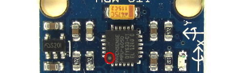 Click to see the full image Click to see the full image
On the telemetry receiver, check the angles of the quadcopter: 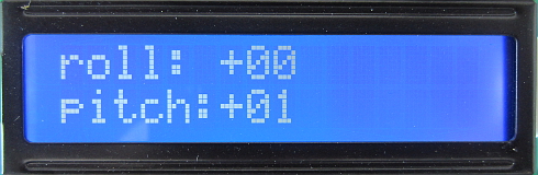
Moving the left side of the quadcopter down should result in a negative roll angle. Moving the left side of the quadcopter up should result in a positive roll angle. Moving the nose of the quadcopter down should result in a negative pitch angle. Moving the nose of the quadcopter up should result in a positive pitch angle. If you don't have a telemetry system you could also check the angles with the test program (function 'e'). If the motors don't run at the same rpm after the activation sequence (left stick down and yaw left) you can check the following:
Make sure that the ESC's are calibrated. Check the manual of the ESC's on how to perform a calibration and follow the
Check if the motors run at the same rpm with the setup program. If the motors don't start at all after the activation sequence (left stick down and yaw left) you need to increase the motor_idle_speed variable that you can find in the setup part of the flight controller code.
Make sure to test the new setting with the props removed. In the original code the maximum angle is set to approximately 33 degrees. The angle is calculated as follows: 500 - 8 / 15 = 32.8 degrees
Where: To change the maximum angle you need to change the value 15 in the following lines:
pitch_level_adjust = angle_pitch * 15;
13 = 37 degrees Adjust the maximum angle with small steps to see if the quadcopter keeps performing normal.
With my own quadcopters I get a flight time between 15 till 20 minutes with a 3800mAh 3 cell lipo. You can find more information about my testquads on the background infromation (bain) page
It's possible to mount a camera as long as the total weight does not exceed the recommended thrust of the ESC's/motors. However, heavier loads means more prop drag/stall and thus more vibrations. The result is jello and unstable flight behavior. I recommend a maximum payload of 200 grams.
No, the YMFC-32 is designed for the STM32F103C8T6 microcontroller. The code will simply not compile for other microcontrollers. No, the YMFC-32 is designed to work with the following sensors:
If you want to use other sensors you need to modify the code yourself based on the datasheet of the sensor that you want to use. Make sure that the sensor that you are using outputs the same data as the sensors listed above. Otherwise the used algorithms in the YMFC-32 will not work. Make sure that you have the right motor, propeller and battery combination. The motors listed in the material list are 1000kV motors. They can handle 10 inch props. However, I recommend 8 inch props. If you use 2000kV motors for example it's not possible to use 10 inch propellers when using a 3 cell lipo. 2000kV motors run at a higher rpm and will produce lift when idling and overload the ESC at full throttle. When you use 2000kV motors it's recommended to use 5 or 6 inch props. When the barometer is placed at the same height as the propellers a high pressure pocket of air will form around the barometer when the quadcopter is flying in the ground effect. This high pressure air pocket will have a negative effect on the altitude hold function. You can recognize this by fast motor rpm increase/decrease when flying in the ground effect. It's always a good idea to mount the barometer a few centimeters above the propellers. Yes, that is possible. however you need to provide 5V to the various sensors, STM32, receiver, telemetry transceiver and so on via an external voltage regulator like this:  1 x Mini DC 7~28V to DC 5V step-down converter 1 x Mini DC 7~28V to DC 5V step-down converter
Connect the input of the voltage regulator to the flight battery and the 5V output to the connection point in the schematic that normally is powered by the BEC of the ESC. If the channel input is not working or the channel inputs are unstable when testing it with the setup program function 'a', check the following:
If you use the serial method for uploading and you get the error below the Arduino IDE cannot initialize the STM32 for upload. Please watch the following video that explains the basic steps of uploading a program to the STM32 with the Arduino IDE:
Failed to init device. The LEDs on the YMFC-32 quadcopter will indicate any errors during startup or flight. In this section you can find more information about the errors Errors at startup Error 1 - MPU-6050 does not respondAt startup the software will test the I2C communication with the MPU-6050. If the MPU-6050 does not respond correctly the error status is 1. Check the I2C bus with the setup program and check the I2C connections. Error 2 - HMC5883L does not respondAt startup the software will test the I2C communication with the HMC5883L. If the HMC5883L does not respond correctly the error status is 1. Check the I2C bus with the setup program and check the I2C connections. Error 3 - MS5611 does not respondAt startup the software will test the I2C communication with the MS5611. If the MS5611 does not respond correctly the error status is 1. Check the I2C bus with the setup program and check the I2C connections. Error 4 - No receiver connectedAt startup the PPM signal of the receiver is checked. The first 4 channel must be above 1000us. If no signal is detected the error output will be 4. Check the receiver inputs with the setup program and check if all the inputs are stable. If you have stable inputs with the setup program but not with the flight battery connected you might have a poor ground (-) from your receiver to the STM32. Double check all the connections. Errors during flight Error 1 - Low battery warningLow battery warning means that the flight battery voltage is low. The YMFC-32 is set to 10.5V by default. You can change the low battery voltage warning in the setup part of the program. Please note that a low voltage is not the same as battery capacity. When using poor LiPo battery's the internal resistance causes the voltage to drop faster. High quality battery's keep their voltage and drop very fast when the full capacity is used. A low battery voltage can damage the battery and causes the quadcopter to become unstable. Some ESC's have a cut-off function that causes them to lower their RPM when the battery is getting low. So make sure that you land the quadcopter as fast as possible. Error 2 - Program loop exceededThe main program loop of the YMFC-32 has a fixed refresh rate of 250Hz. This means that every program loop takes 4000us. These 4000us cannot be exceeded as it will influence the angle calculations and make the quadcopter unstable. If you change the code you have to make sure that the main loop will not exceed the 4000us. Most likely this error is caused by a Serial.print() command or something simmilar. Error 3 - Accelerometer calibration angle exceededDuring the accelerometer calibration sequence (both sticks moved to the top left) the accelerometer offset is registered. This calibration is needed to set the roll and pitch angle to 0 degrees when the quadcopter is spirit level. If the MPU-6050 is not mounted completely flat or the MPU-6050 exceeds the factory specifications the maximum offset is exceeded and the error 3 is shown. This is to make sure that the MPU-6050 is mounted correctly. Check is the MPU-6050 is mounted flat and level on the breakout board and quadcopter. Check the output of the accelerometer with the setup program and make sure that it's within factory specifications.
Open
If the error persists you need to replace the MPU-6050. Error 4 - GPS watchdog timer exceeded during GPS holdThe GPS outputs a new latitude and longitude location every 200 milliseconds. Also known as a 5Hz refresh rate. After every valid GPS position the GPS watchdog timer is reset to 0 and starts counting again. If the watchdog timer is not reset before it reaches 1000 milliseconds and the quadcopter is flying in GPS hold mode , error 4 is indicated by the LED and telemetry system. This error means that the GPS has lost its GPS position and the quadcopter cannot fly in GPS hold mode. The flight mode is automatically set back to altitude hold. To prevent this error make sure that the GPS has a reliable signal and uses 8 or more satellites for the latitude and longitude lacations. Error 5 - manual_takeoff_throttle not in rangeIf you use the manual_takeoff_throttle in the settings it must be set between 1400 and 1600. Set the manual_takeoff_throttle variable to 0 to disable the manual throttle setting. Error 6 - No take-off detectedAfter the start sequence (throttle stick to the bottom left location) the motors will start to spin. When you increase the throttle to half way the motor rpm will automatically increase up to the point the quadcopter takes off. The lift-off is detected with the accelerometer. This method will set the throttle hover point to approximately half throttle. If the throttle pulse tot the ESC's is larger than 1750 and no take-off is detected error 6 is indicated by the LED and telemetry system. This will happen when the quadcopter is too heavy for the motors or when the props are not mounted. You can test if the quadcopter hovers at around 1500 microsecond pulse by setting the manual_takeoff_throttle to 1500. After that check if the quadcopter hovers around the center throttle stick position. Setting the manual_takeoff_throttle variable disables the auto take-off detection. Error 7 - Take-off throttle out of rangeAfter the start sequence (throttle stick to the bottom left location) the motors will start to spin. When you increase the throttle to half way the motor rpm will automatically increase up to the point the quadcopter takes off. The lift-off is detected with the accelerometer. This method will set the throttle hover point to approximately half throttle. If the detected take-off hover throttle is lower than 1400 or larger than 1700 error 7 is indicated by the LED and telemetry system. To prevent this warning you need to make sure that your quadcopter will hover around the 1500 microsecond ECS pulse. You can test if the quadcopter hovers at around 1500 microsecond pulse by setting the manual_takeoff_throttle to 1500. After that check if the quadcopter hovers around the center throttle stick position. Setting the manual_takeoff_throttle variable disables the auto take-off detection. When you use the same hardware as I have listed on my website you should be able to get a stable flying quadcopter. Unfortunately it's possible that you have an unstable quadcopter. This can happen when you use other items as listed on my website. Most instability problems can be solved with tuning the PID settings. However, some instability problems cannot be tuned. For example: you are using 2000kV motors with 10inch propellers. Things that can cause unstable behavior are:
In this video I show the flight capabilities and stability during strong wind conditions.
Normally a quadcopter should hover with the throttle stick around the center position. If you use the parts as listed on my website it should work fine. When the manual_takeoff_throttle is set to 0 the quadcopter should automatically detect its take-off throttle position. As a result the quadcopter should hover with the throttle stick close to the center position. This is very useful when you fly with different payloads or battery's. This will make it easier to switch to the altitude hold mode. However, it's always possible that there is a small offset but this should not be a problem. If the stick is not centered after the automatic take-off detection you can do two things: Change the 1530 to adjust the automatic take off detection in the following line: if (throttle > 1400 && throttle < 1700) takeoff_throttle = throttle - 1530; Change it with 10 points at a time. You can use Ctrl+F to find it. The other option is to set the hover throttle by hand. To do this you need to change the following line: int16_t manual_takeoff_throttle = 0; Change zero to a value where the quadcopter will hover. Keep it between 1400 till 1600. You can use any transceiver set as long as:
Choosing the correct propeller for your motor is very important. Large propellers will overload the motor and ESC's. Small propellers reduce the efficiency and the quadcopter does not hover with the throttle stick in the center position.
If you are using different motors you could check this website: Find the motor that has the same specs as you own motor (kV, amps, voltage, etcetera) and check the propeller data chart for that motor. This will give you a good idea of what propeller suits you motor best.
If your quadcopter drops out of the sky for no reason you should always check if the LED is still flashing and that the STM32 still gets power. If the quadcopter suddenly stops working during flight it's most likely that there is an I2C bus error. This is the only 'normal' reason that the program can come to a complete stop. This can be cause by:
Another reason can might be electromagnetic interference. I made a video about this sebject that you can find here: If everything is working an reliable soldered one of the parts might be faulty.
The YMFC-32 is designed for 3 cell lipo's only. If you want to fly with a 4 cell lipo you need to modify the code yourself. That parts that need attention are:
|
|||||||||||||||||||||||||||||||||||||||