
.net

| Terms of service | ||||
|
Brokking |
.net |
Let's keep it simple |
|
|
|
Project YMFC-3D V2
Click on a question to expand / collapse the answer.
Step 1
First download the complete YMFC-3D version 2 software package: And read the README.txt file that comes with the software package. Step 2
Watch the
Gyro's that that are supported are the L3G4200D, the L3GD20H and the MPU-6050. The orientation of the gyro is not important anymore. You can mount it any way you like as long as the edges of the gyro are aligned with the edges of the quadcopter. Connect the roll, pitch, yaw and throttle output of the receiver to the Arduino Uno ports 8, 9, 10 and 11. Again the order is not important as the software will recognize each separate channel. The connection of the ESC's and direction of the rotation is important:
Step 3Remove the props and upload the setup program to the Arduino Uno. Open the serial monitor at 57600bps and complete the setup by executing the requested actions. It is not necessary to connect a flight battery at this point. Step 4Upload the ESC calibration sketch to the Arduino Uno and calibrate the ESC's as stated in the manual of the ESC. Step 5Mount the propellers and balance them one by one. Step 6Upload the flight controller program to the Arduino Uno and test all the specific functions by holding the quadcopter firmly in your hand.
The quadcopter is started with a specific stick sequence: Step 7
Improve the standard PID settings. For example like I do here:
Step 8
If you would like to learn more about the technical background of the software you might want to watch the other
During setup it might happen that an error accurse. Below you can find detailed information about the possible errors. Error 1: No valid receiver signals found.At startup the setup software is detecting valid receiver pulses on digital inputs 8, 9, 10 and 11. A pulse is valid when it is longer than 900 and shorter than 2100 microseconds. Cause / solution: 1) The receiver outputs: roll/aileron, pitch/elevator, yaw/rudder and throttle need to be connected to the digital inputs 8, 9, 10 and 11. The order is not important. 2) Make sure that the receiver is correctly connected / bound with the transmitter. 3) Turn on the transmitter Error 2: No stick movement detected in the last 30 seconds.At some point the setup software request the user to move the stick that corresponds with the specific quadcopter action. The setup software scans the digital inputs to check if there is a change in pulse length. A valid movement is detected when the pulse is longer than 1750 or shorter than 1250 microseconds. Cause / solution: 1)Move the stick all the way to its end stop. 2)The receiver outputs: roll/aileron, pitch/elevator, yaw/rudder and throttle need to be connected to the digital inputs 8, 9, 10 and 11. The order is not important. 3)Turn on the transmitter Error 3: No gyro device found.The setup software cannot get a valid Who_am_I reaction from the gyro. The setup software searches for the gyro's:
MPU-6050 on address 0x68/104 and 0x69/105; During detection the setup software requests a Who_am_I reaction. If the gyro does not response or the Who_am_I value is incorrect the error message appears. Cause / solution: 1)Check if the gyro is connected correctly to the Arduino Uno.
2)Make sure that the gyro Is 5V compatible. Otherwise the gyro needs to be connected to 3.3V and a level converter should be used. Error 4: No angular motion is detected in the last 10 seconds.At some point the setup software requests the user to move the quadcopter in a specific 45 degree angle within 10 seconds. During this action the setup software is following the movements of the quadcopter. When an angle of more than 30 degree is detected the specific gyro axis is connected to the specific function. When the 30 degree is not reached or the time is expired the error message will appear. Cause / solution: 1)Move the quad within 10 seconds. 2)Make sure that the angle is at least 45 degree. 3)Don't move the quadcopter during calibration. Error 5: EEPROM verification failed.All the data that is collected during setup is stored in the EEPROM of the Arduino Uno (ATmega328P). When the EEPROM writing is done the written EEPROM data is checked. When there is a difference between the EEPROM and the collected data during setup this error message appears. Cause / solution: 1)Make sure that during setup the Arduino Uno supply voltage is 5V. An unstable power supply can cause the EEPROM to get corrupted. 2)The EEPROM is corrupted. Error 6: Receiver channel verification failed.This message appears when not all the receiver channels are assigned to a specific function (pitch, roll, throttle and yaw). Cause / solution: 1)One stick is assigned to two functions. Error 7: Gyro exes verification failed.This message appears when not all the gyro axes are assigned to a specific function (pitch, roll and yaw). Cause / solution: 1)One axis is assigned to two functions. Error 8: I2C clock speed is not set to 400kHzEvery 4 milliseconds a complete program loop is executed. So time is precious. The clock pulse of the I2C bus needs to be set to 400kHz. This way the maximum communication speed is reached.
To change the clock speed of the I2C bus go to the Arduino IDE main folder. Navigate to / open the file twi.h:
On newer Arduino IDE's the Wire library is moved. You can find the twi.h file:
Now find the line: To make the new setting active, upload the setup program again. The complete YMFC-3D package can be downloaded here: Using the Arduino Pro mini is not a problem. This board is loaded with the same processor as the Arduino Uno and will work fine. Please note that the power supply of the Pro Mini might not be sufficient to power the receiver. Using another Arduino like the Arduino Due or Mega2560 is possible but not recommended for beginners. To get it to work you need to modify the code because other controllers use other interrupt registers and i/o pins. The data sheet of the specific microcontroller might be a good starting point. I cannot help you with this because I don't own all the Arduino boards on the market. On the Arduino Uno the A4 and A5 pins are connected to the SDA and SCL respectively. So it does not matter if you use the A4 / A5 pins or the SDA / SCL pins. PID values are hardware specific. So every quadcopter needs its own set of PID values. There are a couple of reasons for that. 1) I like to keep the project as simple as possible. 2) The Arduino IDE configures the PWM frequency @ 500Hz. Not all esc's can handle this. This means that you need to lower the frequency by manipulating the ATmega register. As said before, I like to keep it as simple as possible. 3) 500Hz means you cannot create a 2000us pulse. This means losing precision. I often get the question what hardware is needed to build the YMFC-3D version 2 quadcopter. I made the following list of hardware for your convenience. This list is a suggestion and it's your own responsibility to ensure that the products meet your specific requirements. But this list should work with the YMFC-3D version 2 software. Total estimated cost: $150.00
And some small parts like resistors, diode, wire, connector for the battery, etc. At startup the LED turns on solid for 5 seconds. After that the LED starts to blink fast (8Hz) to indicate the gyro calibration procedure. When the gyro is calibrated the LED turns off. If the LED blinks slowly (1Hz) the throttle is not in the lowest position. If the LED stay's on all the time the setup software is not executed correctly or the registers of the gyro are not set correctly. This is normal. The PID controller starts to work directly after startup. When the quadcopter is on the ground the PID controller try's to correct the quadcopter constantly. The quadcopter cannot response because it is on the ground. Therefor the PID controllers start to increase / decrease the motor rpm. Always take off directly after you start the quadcopter. The YMFC-3D V2 flight controller does not have an auto level function because it only uses a gyro. This means that you need to manually level the YMFC-3D quadcopter. The YMFC-3D schematic and software are designed for a 3 cell flight battery (lipo). This type of battery has a maximum output voltage of 12.6V when fully charged. The diode D1 prevents the USB power from going to the ESC's and motors. When powered by a lipo the voltage drop caused by the diode is approximately 0.6V. The voltage divider (R2 and R3 on the schematic) lower the voltage for the analog input. This analog input can handle a maximum input voltage of 5V. ((12.6V - 0.6V) / (1000Ω + 1500Ω)) * 1000Ω = 4.8V If you connect a 4 cell lipo with a maximum voltage of 16.8V the voltage on the analog port of the Adruino will exceed the 5V and can damage the Arduino. To prevent this you need to change the resistors of the divider.
R3 was 1500Ω and needs to be 8200Ω
((16.8V - 0.6V) / (3300Ω + 8200Ω)) * 3300Ω = 4.65V In the flight controller source code the following lines need to be changed:
line 138:
line 204:
line 207:
line 218 till 223:
needs to be changed in: On the schematic only the ground and the signal wire are connected. This is correct. The +5V from the ESC is not connected because the Arduino gets its power directly from the flight battery via the diode D1. In some cases the ground or - doesn't have to be connected like I did in my video. Check with a multimeter if the ground of the battery connection is connected to the ground / - of the esc connection wire. If these are connected the ground of the ESC does not need to be connected to the Arduino because they share the same battery ground. The signal wire of the ESC's are connected to the digital outputs 4, 5, 6 and 7 as shown in the table below.
The receiver should at least have four channels: The signal output pins should be connected to digital inputs 8, 9, 10 and 11 of the Arduino as shown on the schematic. Check the manual of the receiver to check witch are the signal pins of the receiver. To power the receiver connect the battery connection of the receiver to the +5V and ground of the Arduino as shown in the schematic. When you have setup the quad and loaded the final software it is time to test it in your hand. Some people have experienced that their quad is acting violent. Heavy overcompensating and an uncontrollable behavior. This can be caused by electromagnetic interference. In short it means that the current pulses of the ESC's interfere with the Arduino and gyro. A gyro is a very sensitive device that needs a clean power supply. If that power supply is disrupted the gyro gives strange values. This is causing the quadcopter to behave uncontrollable. To prevent this kind of behavior the distance between the ESC's and the flight controller needs to be as large as possible. Don't put you ESC's right under the Arduino or gyro and prevent long wires and breadboards. To test if the gyro is producing normal values you can send the gyro output to a computer. First you need to uncomment line 65: //Serial.begin(57600); to Serial.begin(57600); so it's possible to use the serial monitor.
Set all the PID values to 0 so it is easier to hold the quad stable. Now add the following code directly under line 146: void loop(){
Connect the USB programmer and flight battery. Open the serial monitor and wait for the calibration to complete. Hold the quad firmly in your hand and lift it up from the table. Start the motors and go to half throttle while trying to keep the quad as level as possible. After 5 seconds or so stop the motors. Now copy the serial output into a text file. With Excel you can now make a graph like I did here. 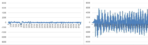 Click to see the full image Click to see the full image
On the left side you can see a 'healthy' gyro and on the right side a gyro that is affected by electromagnetic interference. Both graphs are scaled from -8000 till 8000 for comparison. If your graph is not like the one on the left you probably experiencing electromagnetic interference and you need to prevent this.
The YMFC-3D V2 software is designed to work with any transmitter / receiver that supports a 1520us center pulse. You can find this information in the manual of the transmitter. This means that almost every transmitter will work fine with the YMFC-3D version 2 software. If the setup program stops after the text "Gently move all the sticks simultaneously to their extends" you are probable using the newer Arduino IDE (1.6.x). The program stops because the newer Arduino IDE optimizes the code. Therefore some values need to be declared as volatile.
In the declaration part you need to change the beginning of line 27 from:
to:
|
 YMFC-3D V2.zip