
.net

| Terms of service | ||||
|
Brokking |
.net |
Let's keep it simple |
|
|
|
Project YMFC-32 autonomous Return To Home updateOn this page you can find more information about the YMFC-32 return to home and fail safe update software. It's highly recommended to test the quadcopter with the original software first before you upgrade.  Click to see the full image Click to see the full image
If you encounter any problems during the build or setup please check the
The only change that is necessary to get the new software to run is to setup channel 5 correctly. In the following table the various flight modes and channel settings are displayed. Also don't forget to check out the YMFC-32 autonomous tutorial videos:
Table of contents
The YMFC-32 autonomous holds the following features:
With my own quadcopters I get a flight time between 15 till 20 minutes with a 3800mAh 3 cell lipo. You can find more information about my testquads on the background infromation (bain) page
The YMFC-32 autonomous needs standardized receiver pulses as described in the table below.
Use the table below for the flight modes 1 till 4 and the head lock functions. Check the various functions with the telemetry system.
Always check the flight modes with the telemetry system after finishing the transmitter setup.
If you use the FlySky T6 transmitter as I do you can do a simple internal modification. This modification will give you access to the 4 flight modes of the YMFC-32 autonomous. More information can be found in this video:
Unlike the
The transmitter must have adjustable endpoints and subtrims and a PPM output. So make sure to check the manual of the transmitter for these specific functions. The transmitter that I use myself is this:  Flysky FS-T6 6-CH TX Transmitter Flysky FS-T6 6-CH TX Transmitter
The Flysky T6 has no PPM output. For this I made a PWM to PPM converter that will work with the R6B receiver. You can find more information on
A transmitter with PPM output that works right outof the box is this :
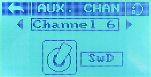
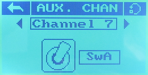
If you use the FlySky i6S you can find detailed setup instructions in the section below. Set the center positions and the end points with the YMFC-32 setup program. All channels must have a 1000 till 2000us travel. The first 4 cahnnels must have a 1500us center position. Use the [End points] and [Subtrim] menus for this. In the [Aux. channels] menu select the following channels and switches. 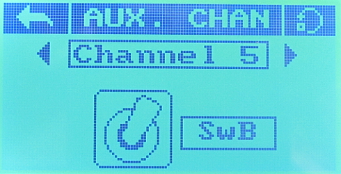
In the [Mix] menu activate the first mixer end set it up as shown below. 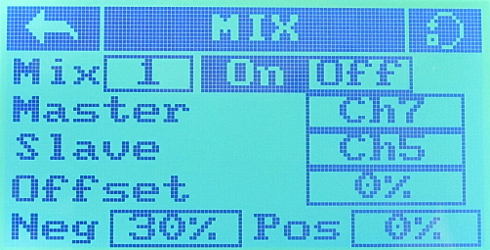
Now the switches on your transmitter will have the following functions. 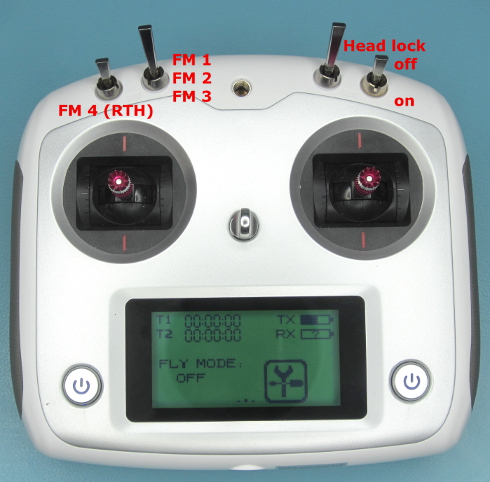
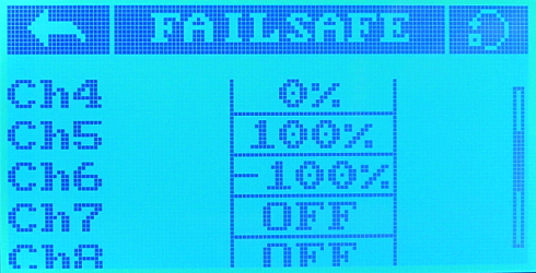
If you activate the following settings in the [failsafe] menu the YMFC-32 will automatically return to home on signal lost when there are enough satellites in use. 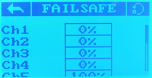
During startup and flight the status LEDs provide valuable information as shown in the picture below:
A more detailed explaination of the errors can be found on the
|
||||||||||||||||||||||||||||||||||||||||||||||||||||||||||||||||||||||||||||||||||||||||||||||||||||||||||||||||||||||||||||||||||||||||||||||||||||||||||||||||||||||||||||||||||||||||||||||||||||||||||||||||||||||||||||||||||||||||||||||||||||||||||||||||||||||||||||||||||||||||||||||||||||||||||||||||||||||||||||||||||||||||||||||||||||||||||||||||||||||||||||||||||||||||||||||||||||||||||||||||||||||||||||||||||||||||||||||||||||||||||||||||||||||||||||||||||||||||||||||||||||||||||||||||||||||||||||||||||||||||||||||||||||||||||||||||||||||||||||||||||||||||||

