
.net

| Terms of service | ||||
|
Brokking |
.net |
Let's keep it simple |
|
|
|
Project YMFC-3D
This version of the YMFC-3D is depreciated and is only available for reference. If you want to build your own Arduino based quadcopter flight controller, check out the
After uploading the YMFC-3D video series questions where pouring in. In this section I filtered the most frequently asked questions and tried to explain them in detail so others can benefit from it.
Click on a question to expand / collapse the answer.
By the questions asked I noticed that most users build the quad according to the provided schematic and directly upload the final code of part 6. Let's call it the fast way. In most cases this won't work and the frustrations immediately kicks in. To get the best result: take your time and watch all the videos first. Try to understand what is going on and make notes while you are paying attention to the small details. 90% of your questions are answered in the videos. In the following steps I will explain how to build and test a YMFC-3D quadcopter. Step 1Watch the first video about the hardware: www.youtube.com/watch?v=2pHdO8m6T7c Start building the hardware setup according to the schematic: www.brokking.net/YMFC-3D/YMFC-3D_schematic.jpg
On the schematic receiver channel: My transmitter that I use in these videos is set to mode 2 (throttle on the left side). If your transmitter is set to mode 1 you need to apply the roll, pitch, yaw and throttle movements to your own transmitter. Remove the props for safety and don't mount them until you are absolutely sure that the quadcopter is working correct. Step 2Watch the second video about receiver inputs: www.youtube.com/watch?v=bENjl1KQbvo And upload the code that is used in the video: www.brokking.net/YMFC-3D/YMFC-3D_receiver.zip
Open the serial monitor and make sure you get the same results as I did. This means for every channel: To get this result use the sub trim and endpoints / limits on your transmitter. Every transmitter is different so you need to check the manual on how to get these results. If you do not set the correct values the quadcopter will not start and / or crash immediately. So these values are extreme important. If your transmitter does not support endpoints / limits you need to modify the code. Check question 06 on how to modify the code. Step 3Watch the third video about the gyro: www.youtube.com/watch?v=nCPEJTUYch8 And upload the code that is used in the video: www.brokking.net/YMFC-3D/YMFC-3D_gyro.zip Open the serial monitor and check if the outputs of the sketch correspond with the movements of the quadcopter. If they don't, check if the orientation of the gyro is correct. Note that the orientation of the L3GD20H is different than the L3G4200D that is shown in the video. If you can't get the desired orientation of the gyro you need to invert or change the gyro signals. Check question 07 on how to do that. If you use the L3GD20H gyro you need to change the address of the gyro. Check question 04 on how to modify the address of the gyro. Step 4Now that the transmitter and gyro are working correct we can test the esc's. First you need to calibrate the esc's. This means that they will work with the full throttle range that is used by the YMFC-3D controller software. Because the transmitter is already setup for the YMFC-3D controller you can calibrate the esc's with the throttle output of your receiver. In most cases this is channel 3. Check the manual of the esc on how to calibrate them. Now watch the forth video about esc's: www.youtube.com/watch?v=fqEkVcqxtU8 And upload the code that is used in the video: www.brokking.net/YMFC-3D/YMFC-3D_esc_output.zip
You should now be able to spin the motors as shown in the video. Check if they run in the correct direction: If a motor does not spin in the right direction change 2 of the 3 motor wires. Step 5Now the quad is build and setup correct for the final code. Watch the fifth video about pid control: www.youtube.com/watch?v=JBvnB0279-Q And the final video: www.youtube.com/watch?v= 2MRiVSyedS4 And upload the final code to the Arduino: www.brokking.net/YMFC-3D/YMFC-3D_Flight_controller.zip You are now able to start the quadcopter. It should response to the transmitter stick movements like roll pitch and yaw and it also corrects the movements of the quadcopter. If everything works you can mount the props and carefully improve the basic pid settings and try to fly it. The YMFC-3D controller does not have an auto level function. You need an accelerometer to auto level the quadcopter. This means that you need to manually level the YMFC-3D quadcopter. The only gyro's that are supported are the L3G4200D and the L3GD20H from ST-Microelectronics. Other gyro's are not supported and I cannot help you with this. There are a lot of gyro's on the market these day's and I cannot keep up with all of them (and I'm not trying either). If you want to use the MPU-6050 or any other gyro you need to modify the code yourself. If you are using the L3GD20H or L3G4200D gyro you can change the I2C address like this: Run the gyro search program to detect the gyro and get the correct address: www.brokking.net/YMFC-3D/YMFC-3D_gyro_search.zip In the Arduino sketch change the decimal value of 105 into your gyro address like this: Wire.beginTransmission(105); ==>> Wire.beginTransmission(new address); And do this for every gyro address. There are 4 changes to make in total. If the led keeps blinking the flight controller does not get the correct input signals. First of all you need to lower the throttle stick. If the led keeps blinking slow the transmitter is not setup correctly. Watch the second video about receiver inputs: www.youtube.com/watch?v=bENjl1KQbvo And upload the code that is used in the video: www.brokking.net/YMFC-3D/YMFC-3D_receiver.zip
Open the serial monitor and make sure you get the same results as I did. This means for every channel: To get this result use the sub trim and endpoints / limits on your transmitter. Every transmitter is different so you need to check the manual on how to get these results. If you do not set the correct values the quadcopter will not start and / or crash immediately. So these values are extreme important. If your transmitter does not support endpoints / limits you need to modify the code. Check question 06 on how to modify the code. If your transmitter is not supporting endpoints / limits you can't set the output of the receiver to 1000 to 2000us for every channel. This means that the flight controller does not get a valid signal and will not start. You need to modify the flight controller code to get the quadcopter to start. Watch the second video about receiver inputs: www.youtube.com/watch?v=bENjl1KQbvo And upload the code that is used in the video: www.brokking.net/YMFC-3D/YMFC-3D_receiver.zip Open the serial monitor and make sure that for every channel mid-stick represents a value of 1500 (+/- 4). Use the subtrim on your transmitter for this.
Now note the minimum and maximum stick value of throttle and yaw. For example:
Upload the final code to the Arduino: www.brokking.net/YMFC-3D/YMFC-3D_Flight_controller.zip Change the throttle value in line 106(in the original code) from: while(receiver_input_channel_3 < 990 || receiver_input_channel_3 > 1020 || receiver_input_channel_4 < 1400){ to while(receiver_input_channel_3 < 990 || receiver_input_channel_3 > 1120 || receiver_input_channel_4 < 1400){
if(receiver_input_channel_3 < 1050 && receiver_input_channel_4 < 1050)start = 1; to if(receiver_input_channel_3 < 1150 && receiver_input_channel_4 < 1140)start = 1;
if(start == 1 && receiver_input_channel_3 < 1050 && receiver_input_channel_4 > 1450){ to if(start == 1 && receiver_input_channel_3 < 1150 && receiver_input_channel_4 > 1450){
if(start == 2 && receiver_input_channel_3 < 1050 && receiver_input_channel_4 > 1950)start = 0; to if(start == 2 && receiver_input_channel_3 < 1150 && receiver_input_channel_4 > 1860)start = 0;
if(receiver_input_channel_3 > 1050){ to if(receiver_input_channel_3 > 1150){ If you can't get the gyro mounted in the desired direction you can always invert the direction or change a gyro axis to get the output of the gyro program to match with the movements of the gyro. To invert a gyro axis ad the following code under the gyro axis data like this: gyro_roll = ((highByte<<8)|lowByte); change this to:
gyro_roll = ((highByte<<8)|lowByte); To change two gyro axis (for example roll and pitch) change this:
lowByte = Wire.read(); into:
lowByte = Wire.read(); I often get the question what hardware is needed to build the YMFC-3D V2 quadcopter. I made the following list of hardware for your convenience. This list is a suggestion and it's your own responsibility to ensure that the products meet your specific requirements. But this list should work with the YMFC-3D V2 software. Total estimated cost: $150.00
And some small parts like resistors, diode, wire, connector for the battery, etc. Using the Arduino Pro mini is not a problem. This board is loaded with the same processor as the Arduino Uno and will work fine. Please note that the power supply of the Pro Mini might not be sufficient to power the receiver. Using another Arduino like the Arduino Due or Mega2560 is possible but not recommended for beginners. To get it to work you need to modify the code because other controllers use other interrupt registers and i/o pins. The manual of the specific microcontroller might be a good starting point. I cannot help you with this because I don't own all the Arduino boards on the market. On the Arduino Uno the A4 and A5 pins are connected to the SDA and SCL respectively. So it does not matter if you use the A4 / A5 pins or the SDA / SCL pins. PID values are hardware specific. So every quadcopter needs its own set of PID values. There are a couple of reasons for that. 1) I like to keep the project as simple as possible. 2) The Arduino IDE configures the PWM frequency @ 500Hz. Not all esc's can handle this. This means that you need to lower the frequency by manipulating the ATmega register. As said before, I like to keep it as simple as possible. 3) 500Hz means you cannot create a 2000us pulse. This means losing precision. When you have setup the quad and loaded the final software it is time to test it in your hand. Some people have experienced that their quad is acting violent. Heavy overcompensating and an uncontrollable behavior. This can be caused by electromagnetic interference. In short it means that the current pulses of the ESC's interfere with the Arduino and gyro. A gyro is a very sensitive device that needs a clean power supply. If that power supply is disrupted the gyro gives strange values. This is causing the quadcopter to behave uncontrollable. To prevent this kind of behavior the distance between the ESC's and the flight controller needs to be as large as possible. Don't put you ESC's right under the Arduino or gyro and prevent long wires and breadboards. To test if the gyro is producing normal values you can send the gyro output to a computer. First you need to add the folowing line under void setup(){ Serial.begin(57600); so it's possible to use the serial monitor.
Set all the PID values to 0 so it is easier to hold the quad stable. Now add the following code directly under line 134: void loop(){
Connect the USB programmer and flight battery. Open the serial monitor and wait for the calibration to complete. Hold the quad firmly in your hand and lift it up from the table. Start the motors and go to half throttle while trying to keep the quad as level as possible. After 5 seconds or so stop the motors. Now copy the serial output into a text file. With Excel you can now make a graph like I did here. 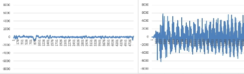 Click to see the full image Click to see the full image
On the left side you can see a 'healthy' gyro and on the right side a gyro that is affected by electromagnetic interference. Both graphs are scaled from -8000 till 8000 for comparison. If your graph is not like the one on the left you probably experiencing electromagnetic interference and you need to prevent this.
For the YMFC-3D version 1 the transmitter needs to have the following features:
Subtrim to set the center position to 1500us You need to check the manual of the transmitter to confirm if these features are available. If this is the case the transmitter should work with the YMFC-3D version 1.
If you already have a transmitter and it does not support subtrim and endpoint / limits you can use the
|
 YMFC-AL project page.